Monitoring relay for step changeover (ÜRF)
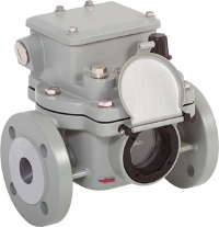 The step switch monitoring relay, also called the step switch safety relay or oil flow rate relay, is a monitoring device for oil insulated step switches with conservator. Its job is to protect the step switch and transformer from damage. The control relay reacts to unacceptably high oil flow rates in the direction of the conservator and sends a signal that immediately cuts off the voltage from the step switch and transformer.
Main types of monitoring relays for step switch:
type 12 (ÜRF 25/10)
type 15 (ÜRF 25)
type 16 (ÜRF 25/10-26)
Overview of monitoring relay types
Nominal pipe bore: 25 mm (1“)
Connection type: flange
The technical parameters given in Table 1 are valid for all standard monitoring relays manufactured by EMB.
| Parameter | Value/data | Notes |
| Voltage | AC 5 V - max. 250 V | consider max. Full construction. power |
| DC 5 V - max. 250 V | ||
| Current | AC 0.01 A - max. 6 A | Cos φ > 0.5 |
| DC 0.01 A - max. 6 A | L/R < 40 ms consider max. Full construction. power | |
| Connected power | AC max.1500 VA | |
| DC max.1250 W | ||
| Electric strength | AC 2500 V | between circuit and ground |
| AC 2000 V (closed, open) | between open contacts | |
| AC 1000 V (switch) | ||
| Temperature range: - ambient temperature | - 40 °C to + 55 °C - 40 °F to + 131 °F | climate test according to DIN EN 60068-2-78: 2002-09 |
| - working area * temperature of insulating liquid | - 40 °C to + 115 °C - 40 °F to + 239 °F | up to +35 °C conditionally option 21 |
| * viscosity of insulating liquid | 1 mm²/s to 1100 mm²/s | |
| Electrical insulating liquid | Mineral oil | |
| Shaking resistance | Vibration: 2.20 Hz, 1 g Shock: 10 g, 11 ms | |
| Compressive strength | 0.25 MPa | |
| Vacuum strength | < 2.5 kPa | |
| Insensitive to magnetic fields | 25 mT | Magnetic balance of any direction and polarity |
| Switching systems: | See Possible switching system designs | |
| - number of main contacts - switching element - valve cover | 1 Magnetic contact is held by a magnet | |
| Valve gate response time | <0.1 s | |
| Insulating fluid flow Nominal pipe inner diameter: 25mm or 26mm | Min. 0.90 to max. 4.00 m/s + 15% | For possible values, see "Ordering data/type designation" |
| Cable fittings | M20x1.5; M25x1.5 | |
| Nominal installation position | 2o to 4o | with rise to expander |
| Degree of protection | IP 56 | |
| Body paintwork | Two-component structural varnish | based on polyurethane |
Additional variants and special versions are shown in Table 2. These additional variants are coded in the "Ordering data/type designation" with the corresponding code.
Other options are available on request.
Variants/special versions
Cable accessories *
| Explanations | Code | |
| M20x1.5: 1 cable fitting and 1 blind bolted connection | 1 | |
| M25x1.5: 1 cable fitting and 1 blind bolted connection | 2 | |
| M20x1.5: 2 cable fittings | 3 | |
| M20x1.5: 2 cable fittings and 1 blind bolted connection (supplied loose) | 3B | |
| M25x1.5: 2 cable fittings | 4 | |
| M25x1.5: 2 cable fittings and 1 blind bolted connection (supplied loose) | 4B | |
| 1/2" NPT: 1 cable accessory and 1 blind bolt connection | 6 | |
| 1/2" NPT: 2 cable ties | 7 | |
| Cable fittings: customer request | 9 | |
Case color *
| Explanations | Code | |
| RAL 7001 (silver grey) | 41 | |
| RAL 7012 (basalt grey) | 42 | |
| RAL 7022 (umber grey) | 43 | |
| RAL 7033 (cement grey) | 44 | |
| RAL 7038 (agate grey) | 45 | |
| RAL 7035 (light grey) | 46 | |
| RAL 7016 (anthracite grey) | 47 | |
| RAL 9002 (grey-white) | 48 | |
| RAL 7032 (pebble grey) | 49 | |
Climatic modification/degree of protection
| Explanations | Code | |
| Climatic design (extremely cold climate with temperatures below – 40 o C)* | 34 | |
| Climatic version (marine climate) | 36 | |
| Protection class IP 66 | 39 | |
Electrical insulating liquid
| Explanations | Code | |
| Insulating liquid silicone oil | 20 | |
| Ester based insulating liquid | 21 | |
Frame
| Explanations | Code | |
| Metal parameter plate | 15 | |
| With air release valve | 97 | |
| With seal (only type ÜRF 25/10-26) | 98 | |
Switching system
| Explanations | Code | |
| The switching system is equipped with two magnetically controlled contacts | 25 | |
| The switching system is equipped with three magnetically controlled contacts | 99 | |
Customer's request
| Explanations | Code | |
| Special wishes of the customer (specific agreements with the customer) | 29 | |
* It is obligatory to specify in each order, other mandatory data given in "Ordering data/type designation"
Ordering data/type designation
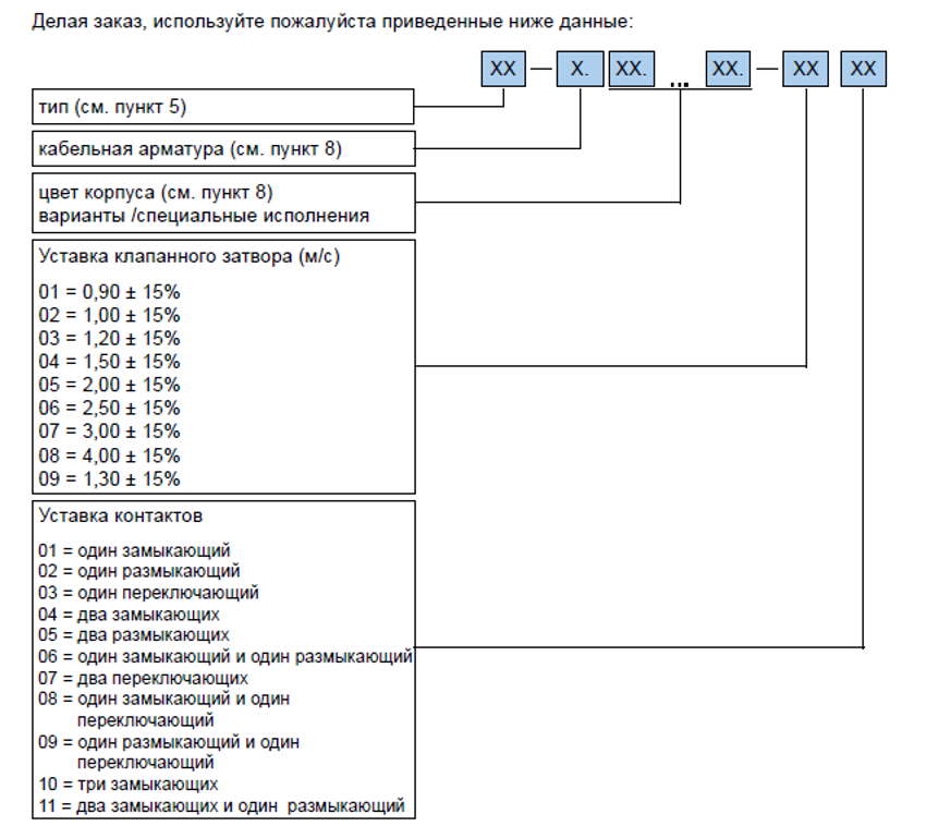
Order example:
The customer requires a monitoring relay type ÜRF 25/10 with cable fittings and a blind threaded connection of size M20x1.5. The valve gate must operate at a flow speed of 2.00 m/s. The switching system must be equipped with two switching elements (magnetic contacts). One switching element must be made in the form of a make contact, the other - in the form of a break contact. The supplied device must be in color RAL 7033.
(Note: The device is suitable for standard mineral oils and has a standard degree of protection IP 56)
According to the above data, the following type designation is available : 12-1.25.44.-0506
Explanation:
12 = ÜRF 25/10
1 = M20x1.5: 1 cable assembly and 1 blind bolted connection
25 = switching system with two magnetic contacts
44 = housing color RAL 7033 (cement gray)
05 = valve gate setting (m/ s): 2.00 m/s +/-15%
06 = adjustment of switching system contacts: one contactor and one contactor