The RS 12/16 switching device is designed for voltage regulation in power transformers under load. Thanks to their high reliability and modular design, the RS 12 / 16 series switching devices can be used in power transformers for process needs. The RS 12/16 switching device kit with motor drive MZ-4.1 meets the requirements of the IEC 60214 1-2003 standard.
Execution options can be for work in countries with temperate, tropical or cold climates, as well as execution according to customer requirements.
1. Basic technical data of switching devices of the RS 12 / 16 series
Table 1 - Basic technical data
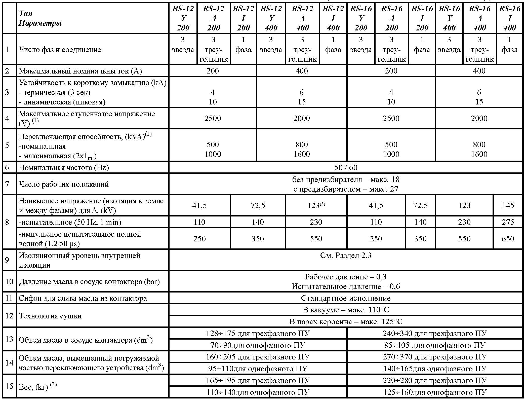
Notes: (1) For more details, see section 1.2 (2) For RS12 Y only. (3) For the exact details of each type of control unit, see the attached general drawing.
1.2. Rated load current (Iu), rated step voltages (Ui), rated switching capacity (PstN).
The rated load current (passing) Iu and the corresponding rated step voltage Ui are determined by the curve for the switching capacity ( Fig. 1 ). When the transformer is overexcited, the maximum step voltage can be increased by 10%, provided that the switching capacity is limited to its rated value.
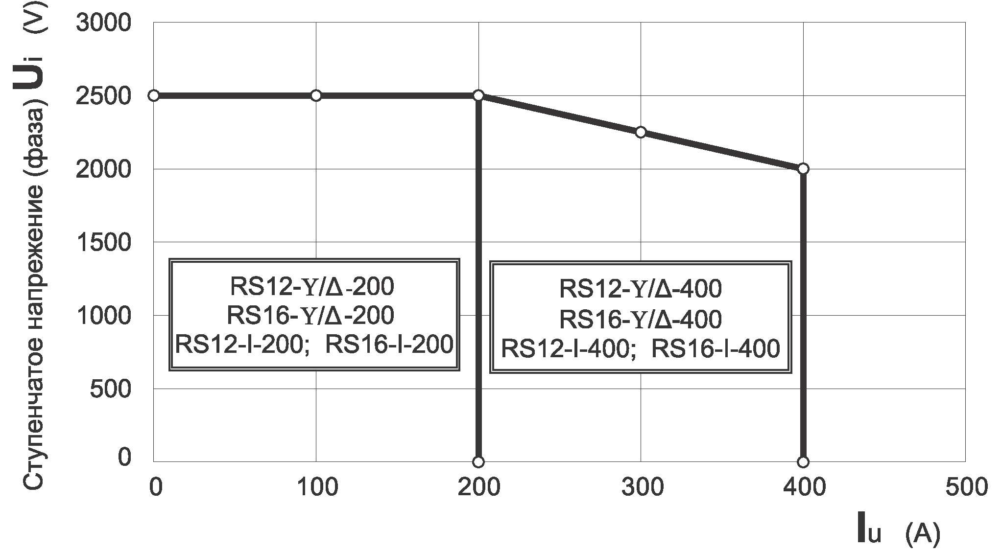
Scheme 1 - Rated switching capacity (stepped passing current Iu [A], stepped voltages [Ui])
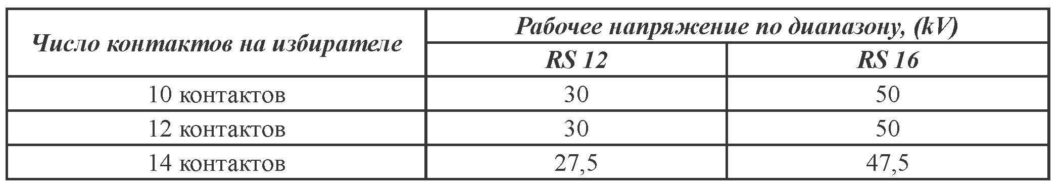
The step voltage is also limited by the maximum voltage over the range, determined on the basis of insulation tests of the selector. The highest operating voltage of the range, determined by the above criterion, shall not exceed the values in the table below:
Maximum switching capacity (Pstmax) is the maximum power at which the switching device can switch. According to IEC 60214-1:2003 m 5.2.2.2. The maximum switching capacity must be at least equal to the rated switching capacity multiplied by 2, i.e.
Pstmax = 2PstN = 2Ium.Ui
Specific switching modes are explained in the general specification of switching devices produced by KHHIB.
1.3 Electrical and mechanical endurance
Electrical endurance is determined by the number of switchings until the limiting wear of the arcing contacts of the contactor. The number of switchings before the revision is given in Table 2.
Electrical endurance is determined when tested with a maximum rated current Ium and the corresponding rated step voltage Ui[V] at cosφ=1.
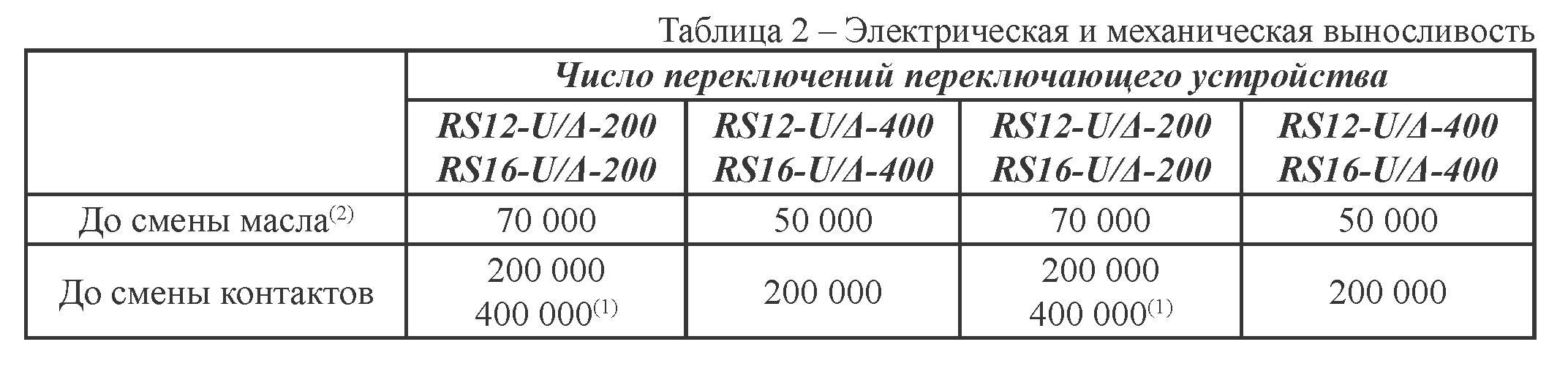
(1) special design
(2) at least: 5 years - for 200 A
3 years - for 400 A
With a passing current below Ium, the number of switchings before changing contacts is determined according to scheme 2.
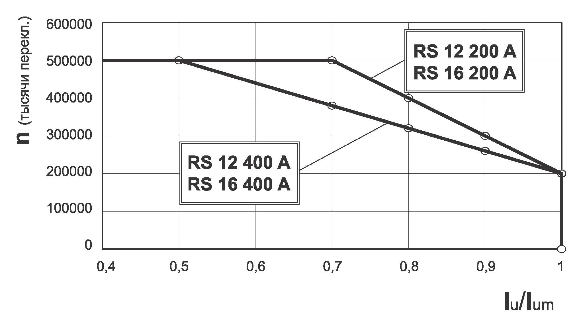
Scheme 2 - Number of switchings before changing contacts
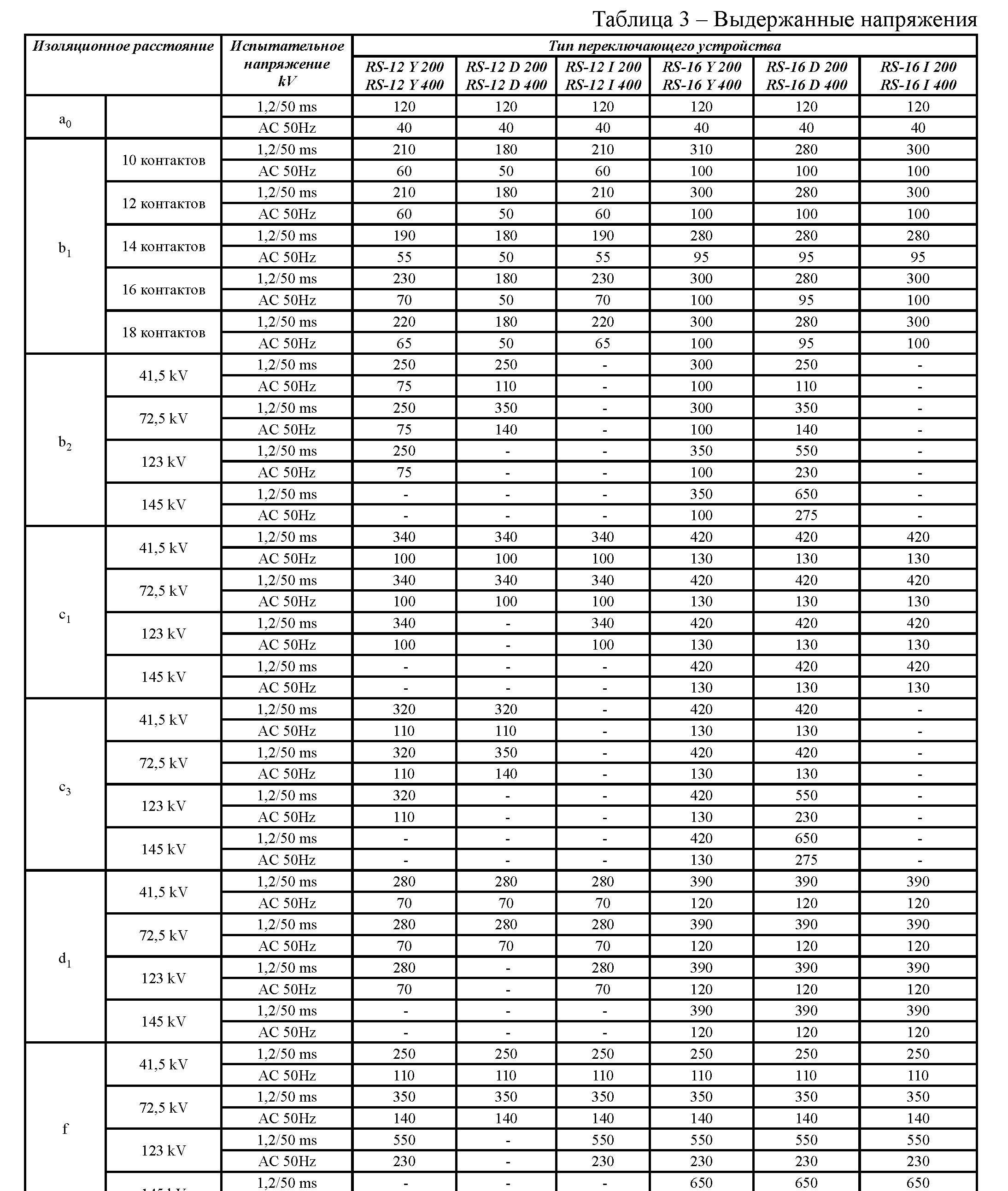
1.4 Insulation level
The insulation level of the switching device is determined by the range of withstand voltages.
The rated withstand voltages to earth are shown in Table 1. These voltages are defined by national and international standards. When selecting a switching device, it is necessary to take into account both the insulation levels to ground and between phases, as well as the insulation level at internal insulation distances. The insulation level of internal insulation is determined by the voltage effects that are obtained from the transformer winding when exposed to voltage during testing and operation. Diagram 3 shows the basic connection diagrams and their typical insulation distances.
Withstand voltages at various insulation distances are given in Table 3. For the correct selection of the switching device, these voltages must be consistent with the voltages that appear during the pulse wave inductive voltage test. The most unfavorable operating position of the switching device must be taken into account. The insulation to ground and the insulation row of the selector are not related to each other and can be selected according to specific requirements.