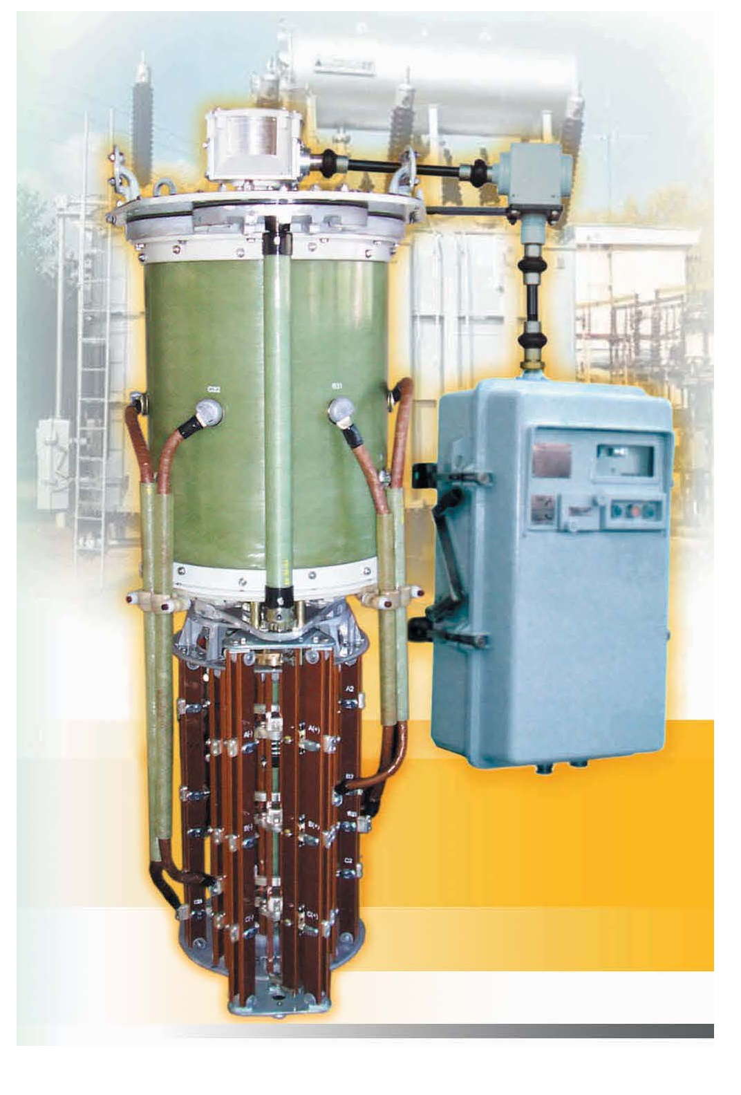
 The RS 5 switching device is designed to regulate the voltage in power transformers under load and is used with delta-connected windings. Due to their high reliability, the switching devices of this series can be used in furnace transformers, electrolysis transformers, etc. The RS 5 switching device set with motor drive MZ-4.1 meets the requirements of IEC 60214 1-2003.
Execution options can be for work in countries with temperate, tropical or cold climates, as well as execution according to customer requirements.
Main characteristics of switching devices of the RS 5 / 5.3 series
Table 1 – Basic technical data of switching devices of the RS 5 / 5.3 series
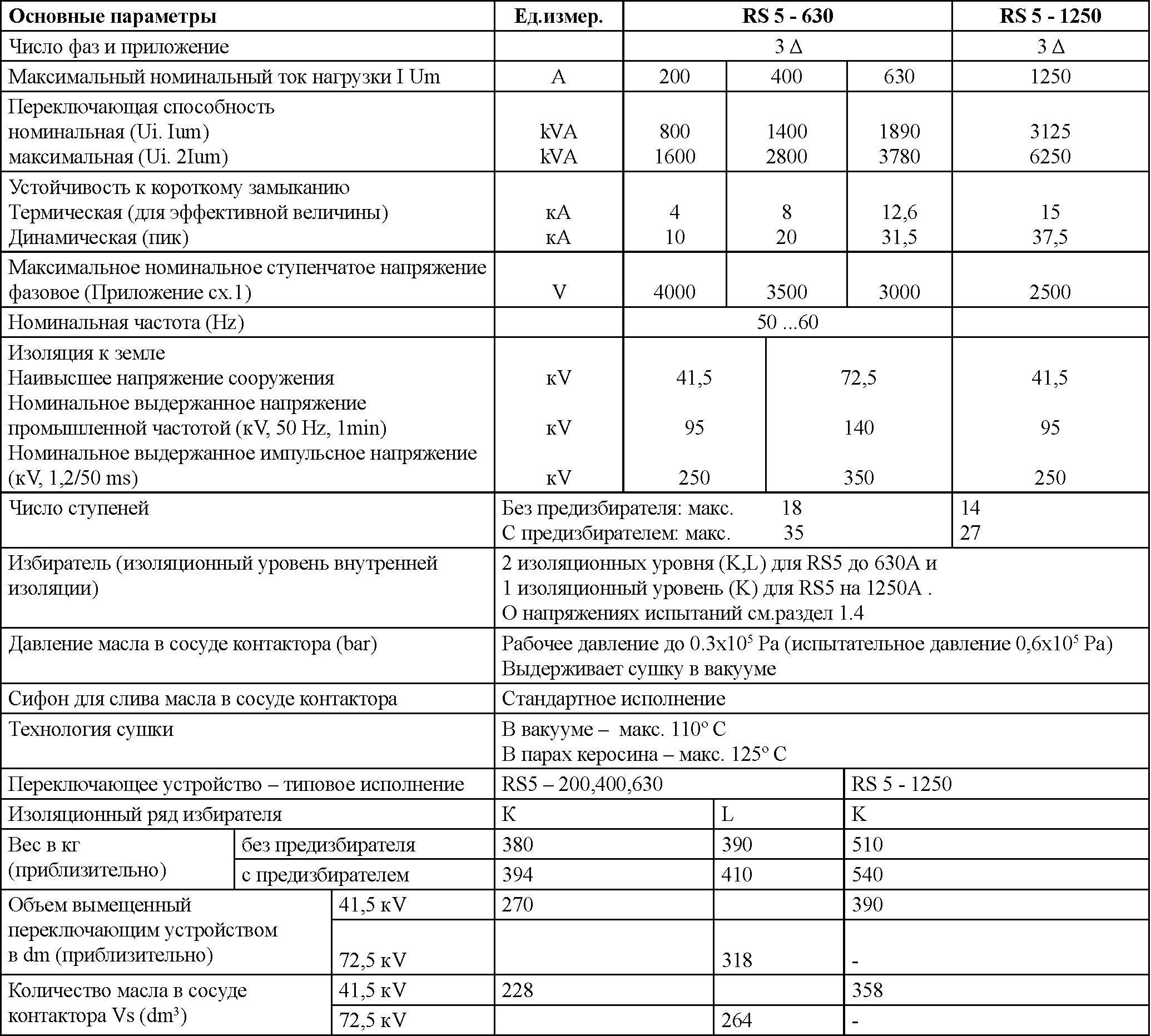
Notes : (1) The RS5 switching device has an oval flange, and the RS5.3 switching device has a round flange. All other technical data are the same for them.
(2) Minimum volume of preservative due to thermal expansion of the oil when the temperature changes from -30ºC to +100ºC: ΔV=0.1Vs+5 (dm3) The RS5
switching device can operate with a rated load at an oil temperature from -25ºC to +115ºC.
1.2. Rated load current (Iu), rated step voltages (Ui), rated switching capacity (PstN).
Table 2 – Rated load current (Iu), rated step voltages (Ui), rated switching capacity (PstN)
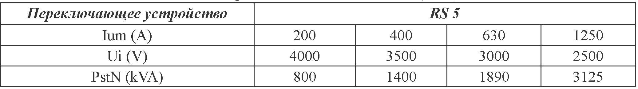
Table 2 shows the maximum values of Iu and the corresponding step voltage Ui and the rated switching capacity PstN. The rated switching load current Iu and the corresponding rated step voltage Ui are determined by the rated switching capacity curve (Fig. 1)
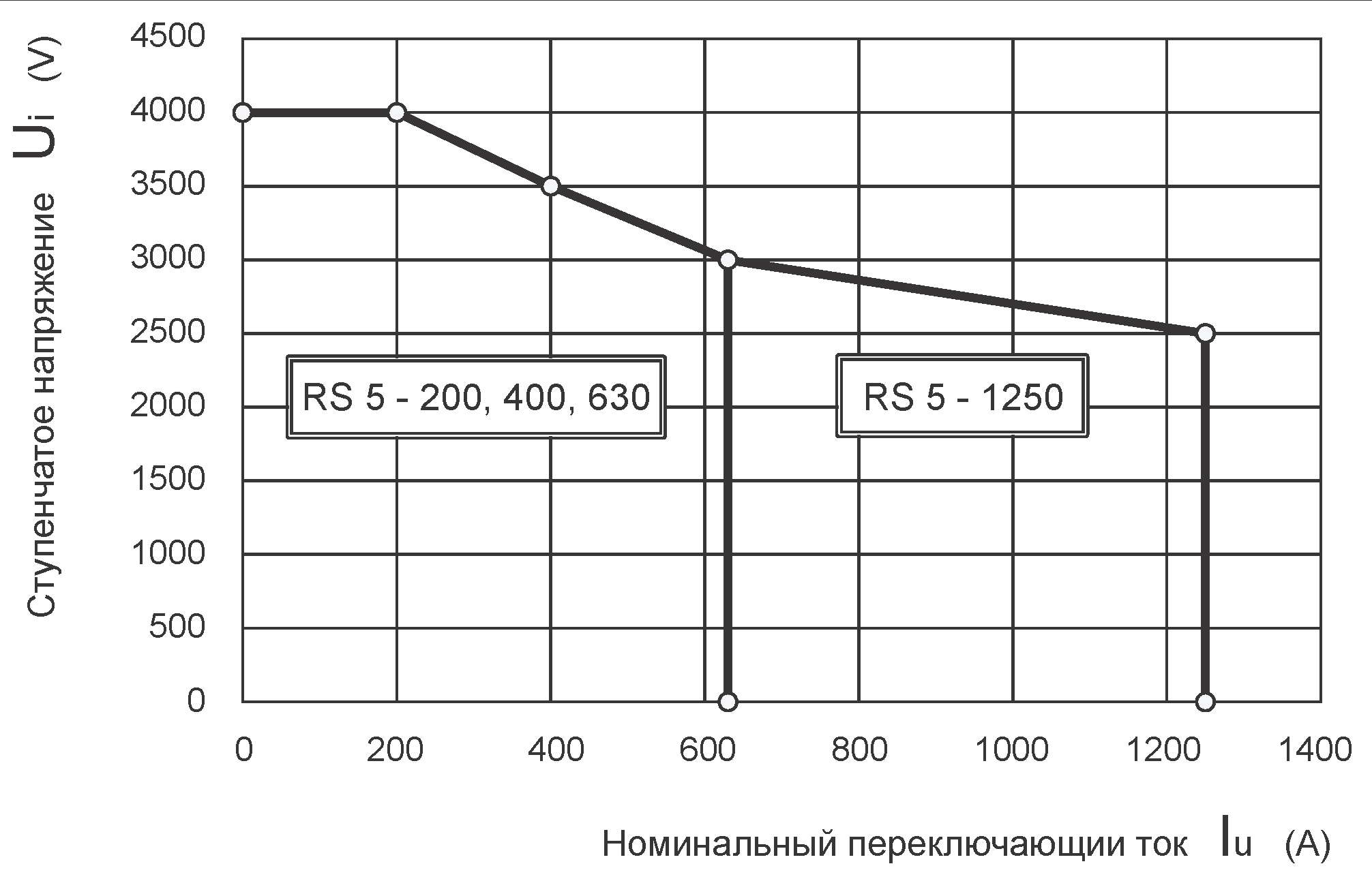
Diagram 1 - Rated switching capacity (rated passing current Iu [A]; rated step
When the transformer is overexcited, the maximum step voltage can be increased by 10%, provided that the switching capacity is limited to its rated value. The maximum switching capacity Pstmax is the maximum power
at which the switching device can safely switch the control winding from one stage to its neighbor.
According to IEC 60214-1:2003 n 5.2.2.2. The maximum switching capacity is confirmed at twice the maximum rated current and the corresponding step voltage and is equal to the rated switching capacity multiplied by 2, i.e. Pstmax = 2Ium.Ui = 2PstN. Specific switching modes are clarified in the general catalog of switching devices produced by HHIB.
1.3 Electrical and mechanical endurance
The electrical endurance of arcing contacts in a contactor depends on many factors related to operating conditions.
Table 3 gives the weighted average values of the number of switchings before revision and before changing contacts, obtained experimentally with real loads on arcing contacts at the maximum rated load current, rated step voltage Ui[V]
and cosφ=1.
Table 3 – Electrical and mechanical endurance
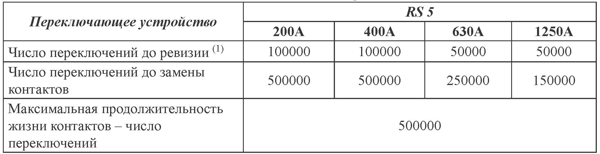
5 years for 200A
(1) At least once every 3 years for 400A
2 years for 630A and 1250A
Details of the number of switching operations before inspection for the various switching devices are given in the RS5/RS5.3 installation and operating instructions .”
At operating current less than Iu max. the number of switchings before replacing contacts is determined according to scheme 2.
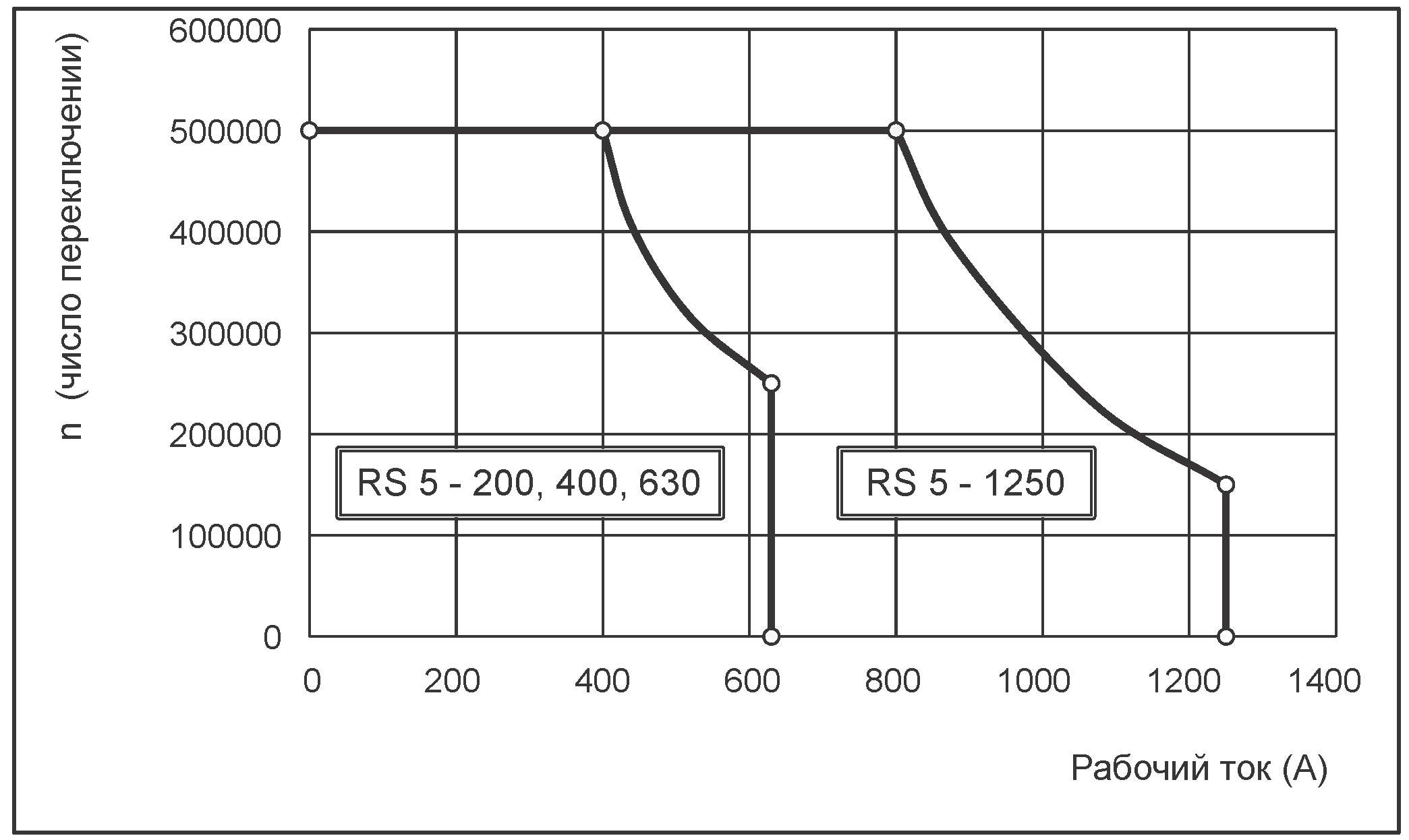
Scheme 2 - Number of switchings before changing contacts
1.4. Isolation level
The insulation level of the switching device is determined by a number of withstand voltages. The rated withstand voltages to earth are shown in Table 1. These voltages are defined by national and international standards. The internal insulation is measured depending on the voltages that are obtained at the deflections of the transformer winding to various parts of the selector, pre-selector and contactor. Diagram 3 shows basic wiring diagrams and typical insulation distances for them. Withstand voltages for various insulation distances are shown in Table 4.
To select the correct switching device, these voltages must be consistent with the voltages that appear in the pulse wave test, the induced voltage test and the 50 Hz applied voltage test. The most unfavorable operating position of the switching device must be taken into account . The insulation to ground and the selector insulation row are not related to each other and can be selected according to specific requirements.