Transformer high-voltage bushings with a voltage of 110 kV with RIP insulation are presented with a porcelain insulator ( STARIP®+ series ) and with a polymer insulator ( STARIP®-Si+ series ) in accordance with the international standard IEC 60137.
Main technical characteristics
| RIP-insulated transformer bushings STARIP®+/STARIP®-Si+ series | 126 | |
| Parameter | U measurement | Meaning |
| Highest operating voltage 50/60 Hz | kV | 126 |
| Partial discharge level | pCL | < 5 |
| Test voltage: 50 Hz;1 min. dry | kV | 255 |
| Lightning impulse test voltage: 1.2/50 µs | kV | 550 |
| Switching test voltage pulse: 250/2500 µs | kV | – |
| Maximum rated current: Imax/450 mm 2 | A | 800 |
| Maximum rated current (removable core): Imax | A | 1600 |
| Maximum rated current fixed core): Imax | A | 2000 |
| Minimum arc path length | mm, SW | 1138 |
| Creepage distance | mm | 3900 |
| Specific creepage distance | mm/kV | 31.7 |
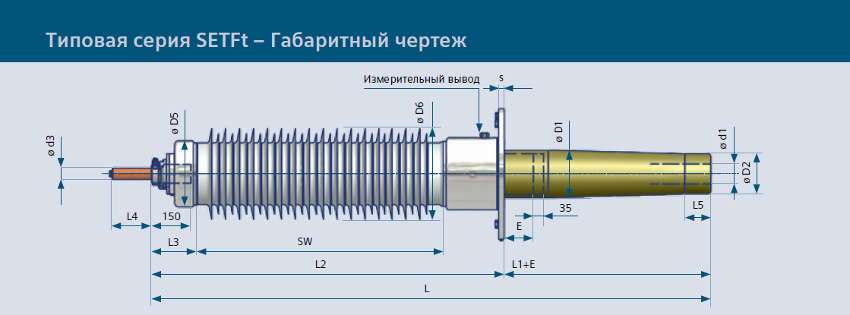
Transformer high-voltage bushings with a voltage of 110 kV with RIP insulation are presented with a porcelain insulator ( ETFt series ) and with a polymer insulator ( SETFt series ) in accordance with the international standard IEC 60137.
Main technical characteristics
| RIP-insulated transformer bushings ETFt/SETFt series | |||
| Technical specifications | U measurement | 123-A | 123-B |
| Highest operating voltage, Um | kV | 123 | 123 |
| Highest operating phase voltage | kV | 71 | 71 |
| Partial discharge level | pCL | < 5 | < 5 |
| Power frequency test voltage 50 Hz, 1 min | kV | 255 | 255 |
| Full wave lightning impulse test voltage 1.2/50 µs | kV | 550 | 550 |
| Switching impulse test voltage 250/2500 µs | kV | - | - |
| Typical test voltages | |||
| Full wave lightning impulse test voltage 1.2/50 µs: negative polarity | kV | 605 | 605 |
| Test voltage of lightning impulse of sheared wave: negative polarity | kV | 666 | 666 |
| Switching pulse test voltage 250/2500 µs in dry condition: negative polarity | kV | - | - |
| Maximum operating current: continuous cable connection, Imax | A | 800 | 1250 |
| Maximum operating current: split current-carrying core, Imax | A | 2000 | 2500 |
| Minimum arc path length, SW | mm | 1138 | 1138 |
| Creepage distance, min. | mm | 3976 | 3976 |
| Leak rate | l/s | 3.5 | 3.5 |
| Test cantilever load | N | 3150 | 4000 |
| Specific creepage distance | mm/kV | 32.3 | 32.3 |
| Dimensions | |||
| D1 | mm | 130 | 150 |
| D2 | mm | 100 | 120 |
| D3 | mm | 290 | 290 |
| D4 | mm | 335 | 335 |
| D5 | mm | 200 | 200 |
| D6 | mm | 280 | 280 |
| L5 | mm | 90 | 90 |
| d1 | mm | 50 | 69 |
| d2 | mm | 65 | 85 |
| l1 | mm | 50 | 50 |
| s | mm | 20 | 20 |
| i | mm | 20 | 20 |
| z | 12 | 12 | |
| a | ° | thirty | thirty |
| Contact terminal dimensions d3 x L4 | mm | ≤ 1250 A = Ø 30 x 90; ≤ 1600 A = Ø 42 x 135; ≤ 2500 A = Ø 48 x 135 | |
| Size for TT installation | |||
| E | mm | 0 | 0 |
| L1 | mm | 350 | 350 |
| L2 | mm | 1503 | 1533 |
| L3 | mm | 155 | 155 |
| Total length, L | mm | 1853 | 1883 |
| Size for TT installation | |||
| E | mm | 300 | 300 |
| L1 | mm | 650 | 650 |
| Total length, L | mm | 2153 | 2183 |
| Size for TT installation | |||
| E | mm | 600 | 600 |
| L1 | mm | 950 | 950 |
| Total length, L | mm | 2453 | 2483 |