 The Buchholz gas relay is an important protection and monitoring device for transformers with liquid dielectric and expander, for arc suppression coils, as well as for the separate monitoring of oil-filled bushings and cable entry boxes. The relay is installed in the cooling circuit of the controlled device and reacts to disturbances such as gas formation, losses and increased flow of liquid dielectric. The variety of types of Buchholz gas relays is based on norms and standards, as well as on special customer requirements. The power rating and design of the device being protected determines the type of relay used. EMB Buchholz gas relays comply with DIN EN 50216-2 (EN 50216-2) and are characterized by easy maintenance, high reliability and a very long service life.
Main types of Buchholz gas relays:
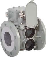
Single-float Buchholz gas relays
Double-float Buchholz gas relays
Technical specifications
The technical parameters given in Table 1 are valid for all Buchholz gas relays manufactured by EMB. Gas relays produced by EMB comply with DIN EN 50216 - 2 (EN 50216-2).
| Parameter | Value/Data | Notes |
| Voltage | AC 5 V - max. 250 V | |
| DC 5 V - max. 250 V | ||
| Current | AC 0.01 A - max. 6 A | cos f > 0.5 |
| DC 0.01 A - max. 6 A | L/R < 40 ms | |
| Connected power | AC max. 1500 VA | |
| DC max. 1250 W | ||
| Electric strength | AC 2500 V | between circuit and ground |
| AC 2000 V (NO, NC) | between open contacts | |
| AC 1000 V (switch) | ||
| Temperature range: | ||
| - ambient temperature | - 40 °C to + 55 °C | climate test according to DIN EN 60068-2-78: 2002-09 |
| - 40 °F to + 131 °F | ||
| - work zone | ||
| * temperature of insulating liquid | - 40 °C to + 115 °C | Others on request |
| - 40 °F to + 239 °F | ||
| Up to +135°С conditionally option 21 | ||
| * viscosity of insulating liquid | 1 mm2/s to 1100 mm2/s | |
| Electrical insulating liquid | mineral oil | others on request |
| Shaking resistance | Vibration: 2-200Hz, 2g | in accordance with class 4M6 according to DIN EN 60721-3-4 |
| Shock: 25g, 6ms | ||
| Compressive strength | 0.25 MPa | |
| Vacuum strength | < 2.5 kPa | |
| Insensitive to magnetic fields | 25 mT | Constant magnetic field of any direction and any polarity |
| Switching systems: | ||
| - number of main contacts | 1 | Several upon request |
| - switching element | magnetic tube | |
| - valve lock | held by magnet | |
| Valve gate response time | <0.1 s | |
| Triggering of the switching system when: | ||
| - accumulation of gas | 200 cm3 to 300 cm3 | Others on request |
| - increased flow of insulating liquid | min 0.65 to max. 3.00 m/s +/-15% | For possible sizes, see " Ordering data/type" in point 12. |
| Pipe diameter Dy: 25 mm, 50 mm, 80 mm | ||
| Cable fittings | M20x1.5; M25x1.5 | Others on request |
| Nominal installation position | 0° to 5° | with rise to expander |
| Degree of protection | IP 56 | Others on request |
| Body paintwork | Two-component structural varnish | Based on polyurethane |
Other options are below. These additional special versions are coded in the "Ordering data/type designation" with the corresponding code. Additional options and special designs are listed below. They are coded with the corresponding codes in the ordering data/index.
Other options are available on request.
Variants/special versions
Cable fittings with threaded connection *
| Explanation | code |
| M20x1.5: 1 cable fitting with threaded connection and 1 blind bolted connection | 1 |
| M25x1.5: 1 cable fitting with threaded connection and 1 blind bolted connection | 2 |
| M20x1.5: 2 cable fittings with threaded connection | 3 |
| M20x1.5: 2 threaded cable fittings and 1 additional blind threaded connection | 3B |
| M25x1.5: 2 cable fittings with threaded connection | 4 |
| M25x1.5: 2 threaded cable fittings and 1 additional blind threaded connection | 4B |
| M20x1.5: 1 Harting electrical connector and 1 blind bolt connection | 5 |
| 1/2" NPT: 1 cable gland with threaded connection and 1 blind bolted connection | 6 |
| 1/2" NPT: 2 cable ties with threaded connection | 7 |
| Cable fittings with threaded connection: customer request | 9 |
Buchholz gas relay NM series
| Buchholz gas relay with analog gas volume detection (two-float gas relays only, Please note: explanations for code 60) | 60 |
Case color *
| Housing color RAL 9006 (white aluminum) | 40 |
| Housing color RAL 7001 (silver grey) | 41 |
| Housing color RAL 7012 (basalt grey) | 42 |
| Housing color RAL 7022 (umber grey) | 43 |
| Housing color RAL 7033 (cement grey) | 44 |
| Housing color RAL 7038 (agate grey) | 45 |
| Housing color RAL 7035 (light grey) | 46 |
| Housing color RAL 7016 (anthracite grey) | 47 |
| Housing color RAL 9002 (grey-white) | 48 |
| Housing color RAL 7032 (pebble grey) | 49 |
Climatic modification/degree of protection
| Climatic design for extremely cold outdoor climatic conditions below - 40 °C | 34 |
| Climatic version for offshore | 36 |
| Climatic design for aggressive industrial climatic conditions | 36B |
| Protection class IP 66 | 39 |
Electrical insulating liquid
| Insulating liquid silicone oil | 20 |
| Ester based insulating liquid | 21 |
Frame
| Metal parameter plate | 15 |
| With oil drain screw (double-float gas relays only) | 28 |
| With pre-installed Harting connector (The specific option is documented by the letter after the code. For further information, please request special documentation.) | 59 |
Switching system
| The upper switching system is equipped with two magnetically controlled reed switches | 35 |
| The lower switching system is equipped with two magnetically controlled reed switches | 25 |
| The upper and lower switching systems are equipped with two magnetically controlled reed switches each | 33 |
| The lower switching system is equipped with three magnetically controlled reed switches | 99 |
| The upper switching system is equipped with two magnetic reed switches, the lower switching system is equipped with three magnetic reed switches | 55 |
| Two Stage Gas Alarm System (Please Note: Explanations for Code 17A) | 17A |
| Testing switching systems with compressed air and a test button (double-float relays only, Please note: explanations for code 32) | 32 |
| The valve gate is held in the actuation position (double float relays only, Note: Explanations for code 23 and 24) | 23 |
| Execution according to the RWE model (only two-float relays, Please note: explanations for codes 23 and 24) | 24 |
| Version E.ON (only two-float gas relays, Please note: explanations for code 23 and 24) | 24B |
| Massive float (insulating fluid flow max. 1.50 m/s ± 15%) | 16 |
| Alarm for gas accumulation between 250 and 300 cm³ | 18 |
Customer's request
| Special wishes of the customer (specific agreements with the customer) | 29 |
Ordering data/typical value
When placing an order, please use the key below:
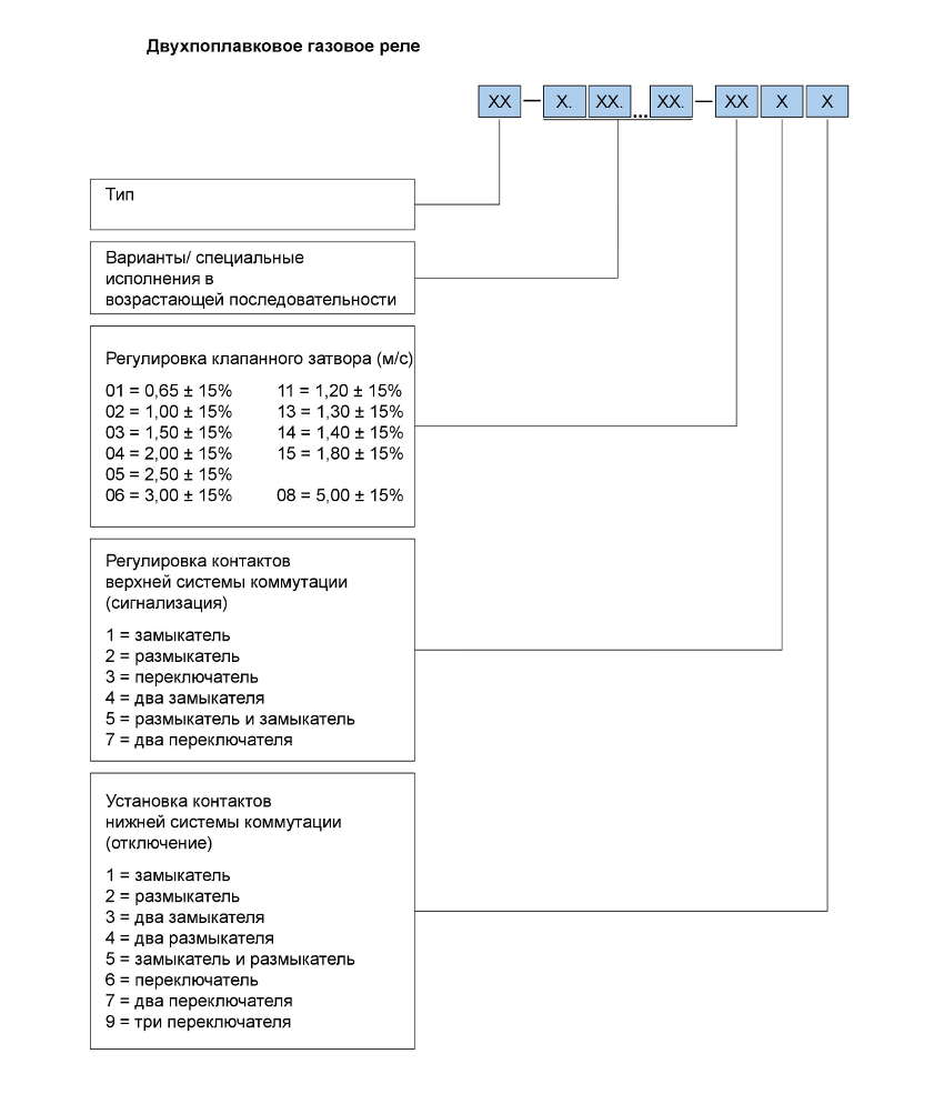
Order example for a two-float gas relay:
The customer requires a two-float gas relay type 10 (BF 80/Q) with threaded cable fittings and a blind bolted connection of size M20x1.5. The valve gate must operate at a flow speed of 1.50 m/s. The upper switching system must be equipped with a switching element (magnetic reed switch), the lower switching system must be equipped with two switching elements (magnetic reed switches).
The upper switching element must be made in the form of a contactor, the lower - in the form of two contactors. The supplied unit must be in RAL 7033 color and have an oil drain screw.
Type designation: 10-1.25.28.44.-0313
Explanation: 10 = double-float gas relay type 10 (BF 80/Q)
1 = M20x1.5; 1 cable gland with screw connection and 1 blind connection
25 = bottom switching system with two magnetic reed switches
28 = with oil drain screw
44 = housing color RAL 7033 (cement grey)
03 = valve shutter response value 1.50 m/s ±15%
1 = installation of contacts of the upper switching system: 1 contactor
3 = installation of contacts of the lower switching system: 2 contactors